AutoCAD Tips: Mastering Annotative Objects for Text and Dimensions in AutoCAD

Tutorial Objectives:
This tutorial will teach you how to use annotative text and dimensions in AutoCAD. Annotative objects automatically scale based on the viewport scale, allowing you to maintain consistent text and dimension sizes across multiple viewports in a layout.

Understanding Annotative Objects

What are Annotative Objects?
In AutoCAD, annotative objects are designed to be scaled automatically based on the scale of your drawing or viewport. This feature is especially useful when working with text, dimensions, and hatches that need to appear at a consistent size on printed drawings.

Why Use Annotative Objects?
– Eliminates the need to create multiple copies of text and dimensions for different scales.
– Ensures that annotations are readable and consistent in different viewports.
– Saves time and reduces errors in scaling manually.

Creating Annotative Text

Step 1: Define Annotative Text Style
1. Type `STYLE` and press Enter to open the Text Style Manager.
2. Click New, name the text style as `Annotative Text`, and check the box labeled Annotative
3. Set the font and size (e.g., 1/8” or 3 mm depending on your units).
4. Click Apply and then Close.

Step 2: Place Annotative Text
1. Type `TEXT` and press Enter.
2. Specify a start point and enter your text (e.g., “Annotative Text Example”).
3. Notice the Annotative Icon (a small scale symbol) next to the text, indicating that it’s annotative.

Step 3: Assign Annotation Scale
1. Select the text object.
2. In the Properties panel, find the Annotative Scale section.
3. Add multiple scales (e.g., 1:1, 1:2, 1:4) using the Annotation Scale dropdown.

Tips:
Use the `ANNOAUTOSCALE` command and set it to 1 to automatically add the current annotation scale to all annotative objects.

Creating Annotative Dimensions

Step 1: Define Annotative Dimension Style
1. Type `DIMSTYLE` and press Enter to open the Dimension Style Manager.
2. Click New, name it `Annotative Dim`, and check the box labeled Annotative.
3. Go to the Text tab and set the text height to 1/8″ (or 3 mm).
4. In the Fit tab, ensure that Scale dimensions to layout is selected.
5. Click OK and Set Current, then close the dialog.

Step 2: Place Annotative Dimensions
1. Type `DIMLINEAR` and press Enter.
2. Select two points on the rectangle to place the dimension.
3. The dimension will automatically be assigned the current annotation scale.

Testing Annotative Scaling in Viewports

Step 1: Create Layout Viewports
1. Go to the Layout tab and type `MV` (for Make Viewport).
2. Draw two viewports side by side on the layout.

Step 2: Set Different Scales for Each Viewport
1. Click on the first viewport and set its scale to 1:1.
2. Click on the second viewport and set its scale to 1:2.

Step 3: Observe the Annotative Objects
– The text and dimensions should automatically resize based on the viewport scale, appearing consistent and readable in both viewports.

Tutorial Tips:
If the annotations don’t display correctly, use the command `ANNOUPDATE` to refresh them.

Common Issues and Troubleshooting

1. Annotations Not Scaling Properly:
– Ensure the objects are set as annotative in their properties.
– Verify that the annotation scales have been applied correctly.

2. Text or Dimensions Not Visible:
– Check if the viewport scale is listed in the object’s annotation scale list.
– Use `ANNOALLVISIBLE` and set it to 1 to display all annotative objects, regardless of the current scale.

3. Text Overlapping or Cluttered:
– Adjust the annotation scales or reposition objects to avoid overlaps in different viewports.

By mastering annotative text and dimensions, you can ensure consistent annotation sizes across different scales and viewports, making your drawings more professional and easier to read. This is a powerful skill for anyone looking to streamline their AutoCAD workflow.

Interested in learning more AutoCAD content?

AutoCAD Tip: New in 2025 are Tech Previews – Try the latest Block Object Detection

AutoCAD Tip: New in 2025 are Tech Previews – Try the latest Block Object Detection

Tech Previews

Tech Previews, also referred to as technical or technology previews, offer you the opportunity to access new features in AutoCAD before they’re officially released. By participating in Tech Previews, you can explore and test out the functionality of these new features and provide valuable feedback to the AutoCAD product team.

During a Tech Preview, the preview features are fully functional and ready to be used. Since these features are still under development, additional capabilities and improvements may be available for testing. This provides you a chance to evaluate how these features can benefit your workflows and projects.

Unlike Beta programs, Tech Previews are open to everyone, allowing active participation and contribution to the ongoing improvement of the feature’s capabilities. Your feedback is important in shaping the final version of the feature.

AutoCAD is dedicated to continuously improve and evolve the preview feature until it reaches a stage where it’s ready to be released as a regular feature, thereby transitioning out of the Tech Preview phase.

AutoCAD 2025 includes a technology preview that uses machine learning to scan your drawing for objects that can be converted into blocks.

When you start Object Detection, the drawing’s geometry is sent to the AutoCAD machine learning service for recognition. Once the service has analyzed the drawing, the palette will notify you if any objects have been detected that can be converted to blocks. To further inspect and assess the identified instances, click Review Objects.

In review mode, the Detection toolbar is displayed at the top of the drawing window. This toolbar provides various options for navigating and managing detection results. The detection results are grouped into sets of similar objects. A set represents a group of similar detected objects that can be converted into instances of a single block.

Within each set, the primary instance (outlined by a blue border) serves as the block definition when converting into a new block. Alternatively, if you choose to convert into an existing block, the primary instance is used to define the insertion scale and rotation.

You may encounter incorrect sets or instances during detection review. In the following example, a similar object is not detected and included in the set. You can report this error using the Detection toolbar. By reporting errors, you contribute to improving the overall performance and accuracy of the machine learning service.

Key Considerations

Object Detection is a technology preview, which means that the detection capability and functionality will be further enhanced and improved over time.

It’s important to note that Object Detection is optimized for plan-view drawings. The types of objects that AutoCAD can detect are continuously expanding. Currently, Object Detection is best at recognizing the following objects:

  • Single-swing doors
  • Double-swing doors
  • Toilets
  • Bathtubs
  • Urinals
  • Generic lighting symbols
Note: Object Detection relies on machine learning algorithms, so the results may not always be completely accurate or comprehensive.

To optimize detection accuracy as we continue to improve the machine learning algorithm, it’s recommended to set your drawing to real-world units before you start the detection.

While in review mode, the following commands are temporarily blocked:

  • BEDIT
  • COMPARE
  • COUNT
  • COUNTLIST
  • PLOT
  • PUBLISH
  • REFEDIT
  • TRACE
  • XCOMPARE
AutoCAD Tips | Edit Attributes in Excel: Export and Import Attributes [Video: 5.13]

AutoCAD Tips | Edit Attributes in Excel: Export and Import Attributes [Video: 5.13]

In this tutorial, we’ll walk through how to use the Import and Export Attribute tool within AutoCAD to easily export block attribute data to a .txt file that can be quickly edited in Excel. This can save a ton of time if you need to modify multiple attributes of your blocks at one time. It can also come in handy when needing to create parts lists, take offs and quantities.

Using blocks with attributes allows you to export the parameters to a text file that can be manipulated in Excel. The updated parameters can then be loaded into the blocks again. This can only be done if you have the full AutoCAD license with the express tools. Express tools are capabilities that other people programmed but that are included with the full AutoCAD license. Explore and use them to your benefit.

Whats new in AutoCAD 2024

Whats new in AutoCAD 2024

AutoCAD 2024

Whats New

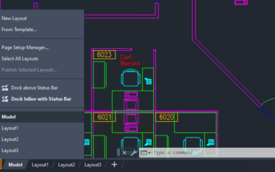
Layout Tab Menu

Layout Tab Menu

Use the new layout tab menu to switch between layouts, create a layout from a template, publish layouts, and more. Right-click a layout name to see more options. Note: Use the Ctrl and Shift keys to select multiple...

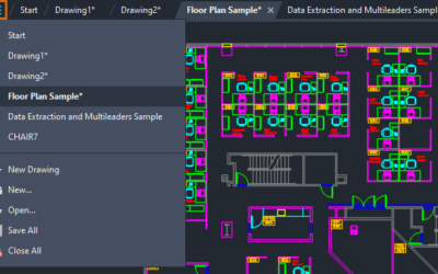
File Tab Menu

File Tab Menu

Use the new file tab menu to switch between drawings, create or open a drawing, save all drawings, close all drawings, and more. Note: The file tab menu replaces the overflow menu. Hover over a file name to see...

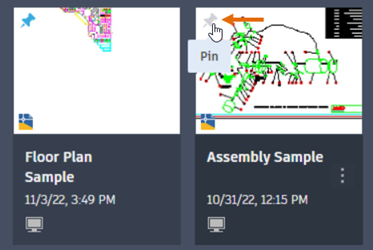
Start Tab Updates

Start Tab Updates

The Start tab continues to be improved in this release including new options to sort and search recent drawings. Recent Drawings Updates The recent drawings list uses smaller thumbnails to allow for more drawings to...

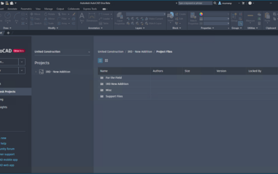
Improvements for Autodesk Docs

Improvements for Autodesk Docs

The following improvements have been made to Autodesk Docs: Improved support and performance when viewing large files on Autodesk Docs. Improved Desktop Connector resulting in improved performance displaying a drawing...

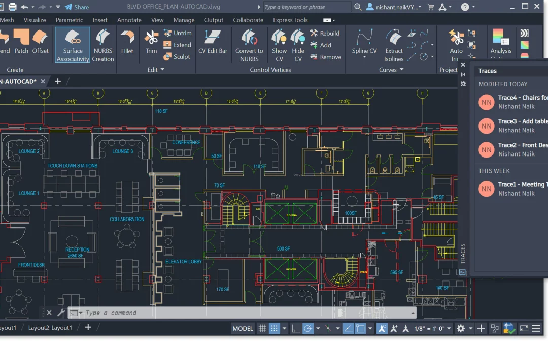
Trace Updates

Trace Updates

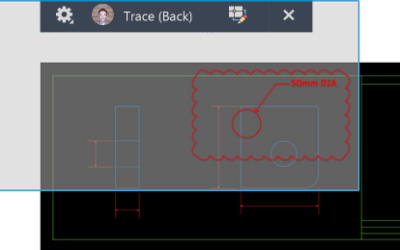
The Trace environment continues to improve and now includes the new COPYFROMTRACE command and new settings controls on the toolbar. New Trace Settings The new COPYFROMTRACE command lets you copy objects from a trace...

Markup Assist

Markup Assist

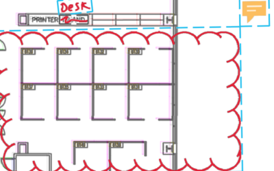
The previous AutoCAD release included Markup Import and Markup Assist, which use machine learning to identify markups and provide a way to view and insert drawing revisions with less manual effort. This release...

Smart Blocks: Replacement

Smart Blocks: Replacement

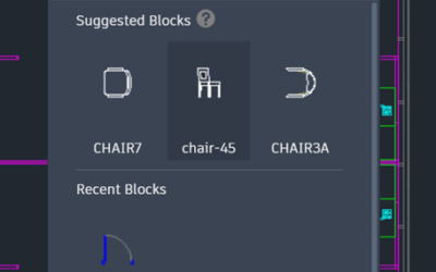
Replace specified block references by selecting from a palette of suggested similar blocks. When you select block references to replace, the product suggests similar blocks for you to select from. When the block...

Smart Blocks: Placement

Smart Blocks: Placement

The new smart block functionality can offer placement suggestions based on where you've placed that block before in the drawing. The new automatic block placement capability is now enabled for blocks inserted using the...

Activity Insights

Activity Insights

Activity Insights provides an understanding of the past actions that you or others have performed with regard to your drawings. Activity Insights tracks events whenever a drawing file is opened and being worked on in...

Send us a message or just call us at 201-792-6300

Lets Connect