Parametric Design in BIM: Unlocking Creativity and Efficiency in Architectural Practice

Parametric Design in BIM: Unlocking Creativity and Efficiency in Architectural Practice

Parametric design is reshaping the architectural landscape by empowering designers to create responsive, adaptable, and highly customizable building components within BIM platforms like Revit. At its core, parametric design leverages mathematical relationships and constraints—known as parameters—to control the form and behavior of digital elements. This approach enables architects to quickly generate multiple design iterations, optimize performance, and tailor solutions to specific project requirements, all while maintaining consistency and accuracy across the model.

The foundation of parametric design in Revit lies in the creation of parametric families—intelligent building components that can be flexed, resized, and adapted without the need for manual redrawing. By defining reference planes and applying dimension parameters, architects set up a flexible framework for geometry. For example, a window family might include parameters for width, height, sill height, and material type. As these parameters are adjusted, the window automatically updates to reflect the new values, ensuring that all instances of the family remain consistent and coordinated throughout the project. This dynamic responsiveness is especially valuable in the early phases of design, where rapid iteration and exploration are essential.

Beyond simple dimensional control, parametric design in Revit supports advanced workflows such as conditional logic, formulas, and nested families. Designers can use mathematical expressions to drive relationships between parameters—such as ensuring that a window’s height is always half of its width, or that a cabinet’s shelf count adjusts automatically based on overall height. These capabilities enable architects to create complex, adaptive components that respond intelligently to changes in the model, reducing the risk of errors and streamlining documentation. Moreover, parametric families can store extensive data, including material specifications, manufacturer information, and cost estimates, further enhancing their utility for project coordination and facility management.

As the demand for intelligent, data-driven design grows, parametric design is becoming an indispensable tool for architects seeking to deliver innovative, efficient, and high-quality projects. By mastering parametric family creation, design teams can unlock new levels of creativity, efficiency, and precision, positioning themselves at the forefront of digital transformation in the built environment.

Robotech CAD Solutions: Expert Training for Parametric Family Creation in Revit

For architects and firms looking to build expertise in parametric design, Robotech CAD Solutions offers comprehensive teaching and hands-on training tailored to creating parametric families in Revit. Their courses cover everything from the fundamentals of parameter setup and reference plane management to advanced techniques such as formula-driven relationships and nested family assemblies. With Robotech’s expert guidance, users can gain the skills and confidence needed to develop flexible, intelligent building components that streamline workflows and elevate project outcomes. Whether you are new to Revit or seeking to expand your capabilities, Robotech CAD Solutions provides the support and instruction necessary to master parametric family creation and drive innovation in your architectural practice.

Parametric Design in BIM: Unlocking Creativity and Efficiency in Architectural Practice

Revit Tutorial: Creating a Simple Parametric Window Family in Revit

Parametric families are essential for architects who want flexibility and precision in their Revit projects. This step-by-step tutorial will guide you through creating a basic, yet fully parametric, window family in Revit—perfect for both beginners and those looking to refresh their skills. By building a window family with adjustable height and width, you can quickly adapt your designs to meet different project requirements and client preferences.

Step 1: Start a New Window Family

Open Revit and go to the File menu. Select New > Family. In the template selection dialog, choose Window.rft. This template is specifically set up for window families and includes the necessary wall host and reference planes.

Step 2: Set Up Reference Planes

Once inside the Family Editor, you’ll see default reference planes for the center (Left/Right and Front/Back). To define the window’s size, add two additional vertical reference planes for the left and right edges, and two horizontal reference planes for the top and bottom edges. Use the Reference Plane tool from the Create tab. Name your new planes “Left,” “Right,” “Top,” and “Bottom” for clarity.

Step 3: Add and Label Dimensions

Use the Aligned Dimension tool to add dimensions between the “Left” and “Right” planes (width), and between the “Top” and “Bottom” planes (height). Select each dimension, click Label, and choose <Add parameter…>. Name these parameters “Window Width” and “Window Height.” Set them as Type parameters so you can create multiple window sizes later.

Step 4: Create the Window Opening

Select the Create tab and choose Void Form > Void Extrusion. Draw a rectangle that snaps to your “Left,” “Right,” “Top,” and “Bottom” reference planes. Lock each side of the rectangle to the corresponding reference plane by clicking the padlock icon. Set the extrusion depth to match the wall thickness or as desired (typically 6″ or 150mm).

Step 5: Add Window Frame Geometry

Next, create the window frame. Use the Solid Extrusion tool to draw a rectangle slightly larger than the void opening, then use another rectangle inside to create the frame’s thickness (for example, 2″ or 50mm). Lock the outer rectangle to the “Left,” “Right,” “Top,” and “Bottom” planes, and set the frame thickness using an Offset or by locking to additional reference planes if you want the frame thickness to be parametric as well.

Step 6: Add Glass Panel

Create another Solid Extrusion for the glass panel. Draw a rectangle inside the frame, locking it to the inner edges of the frame reference planes. Assign a glass material by selecting the extrusion, going to the Properties palette, clicking the small box next to Material, and creating a new parameter called “Glass Material.”

Step 7: Flex Your Family

Before finishing, always “flex” your family to ensure the parameters work. Open the Family Types dialog, change the “Window Width” and “Window Height” values, and click Apply. Confirm that the geometry resizes correctly and remains properly constrained. Adjust any constraints or locks as needed.

Step 8: Add Family Types and Save

In the Family Types dialog, create a few different window sizes by clicking New Type and entering different values for width and height. Save your family, then click Load into Project to use your new window in any Revit model.

Learn More About Parametric Design with Robotech CAD Solutions

Robotech CAD Solutions offers expert-led classes to help you master parametric family creation in Revit, including windows, doors, and other essential architectural components. Their hands-on training covers everything from basic family setup to advanced parametric controls and best practices. Whether you’re new to Revit or seeking to refine your skills, Robotech’s courses provide the guidance and support you need to create powerful, flexible families that enhance your architectural workflow. Explore Robotech’s training programs to unlock the full potential of parametric design in your projects.

Happy modeling!

If you have any questions about Revit or Revit Family Creation, feel free to leave a comment down below and one of our instructors can reach out.

Revit Tutorial: Using View Range Settings in Revit to Control Visibility in Floor Plan Views

Revit Tutorial: Using View Range Settings in Revit to Control Visibility in Floor Plan Views

Welcome to this beginner-friendly tutorial on using View Range settings in Autodesk Revit! View Range is a powerful tool that allows you to control which elements are visible in your floor plan views. By the end of this tutorial, you’ll understand how to adjust these settings to display exactly what you need in your drawings.

What is View Range?

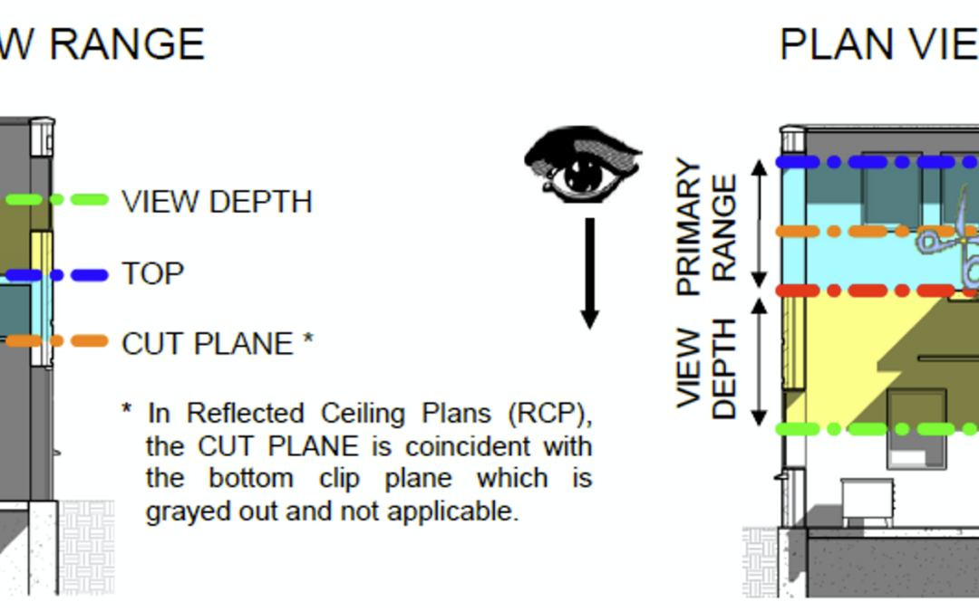
In Revit, the View Range determines how much of the model is visible in a floor plan view. It defines the vertical range (height) of the view and controls which elements are cut, visible, or hidden. Think of it as a “slice” through your building model at a specific height.

Key Components of View Range

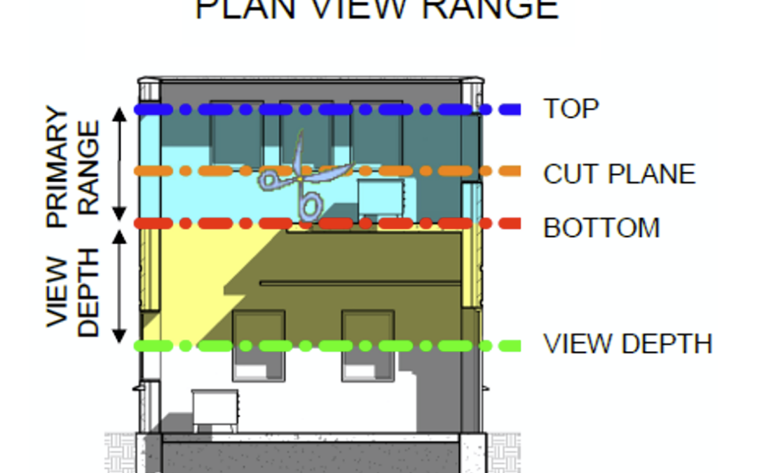
The View Range settings consist of four primary planes:

  1. Primary Range

Top: Defines the upper limit of the view.

Cut Plane: Defines the height at which elements are “cut” (e.g., walls, doors, windows).

Bottom: Defines the lower limit of the view.

  1. View Depth: Extends below the Bottom plane to show additional elements (e.g., foundations or floor slabs).

Step-by-Step Guide to Adjusting View Range


Step 1: Open a Floor Plan View

  1. Open your Revit project.
  2. Navigate to the floor plan view you want to adjust.

Step 2: Access View Range Settings

  1. In the Properties palette, scroll down to the Extents section.
  2. Click on View Range to open the View Range dialog box.

Step 3: Understand the View Range Dialog Box

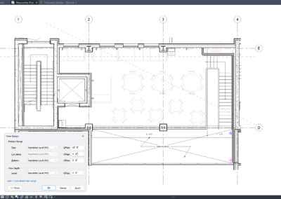
The dialog box will display the following fields:

Top: Set this to the highest level you want to see in the view (e.g., the level above).

Cut Plane: Set this to the height where elements are cut (typically 4 feet for floor plans).

Bottom: Set this to the lowest level you want to see in the view (e.g., the current level).

View Depth: Set this to extend below the Bottom plane if you want to see additional elements.

Step 4: Adjust the Settings

  1. Set the Cut Plane: For most floor plans, set the Cut Plane to 4 feet (1200 mm) to cut through doors and windows.
  2. Adjust the Top and Bottom: Set the Top to the level above and the Bottom to the current level.
  3. Extend the View Depth: If you want to see elements below the floor (e.g., foundations), set the View Depth below the Bottom plane.

Step 5: Apply and Check the Results

  1. Click OK to apply the settings.
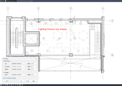
  2. Review your floor plan to ensure the desired elements are visible.

Tips for Beginners 

Experiment: Don’t be afraid to adjust the settings and see how they affect your view.

Use Defaults: Start with the default settings and tweak them as needed.

Check Visibility Graphics: If elements are still not visible, ensure they are not hidden in the Visibility/Graphics settings.

Visual Aid

The images below are an example of how the View Range dialog box looks and how it affects a floor plan view: 

Conclusion 

Mastering the View Range settings in Revit is essential for creating accurate and clear floor plan views. By following this tutorial, you should now feel confident in adjusting these settings to control the visibility of elements in your projects.

Happy modeling!

If you have any questions about Revit or access the View Range, feel free to leave a comment down below and one of our instructors can reach out.

What’s New in Revit 2024.1.1

What’s New in Revit 2024.1.1

Autodesk has recently released a new update for Revit 2024 that addresses 25 quality issues improving functionality and stability. This is an important update for all Revit 2024 (all versions) users, and we recommend that everyone using a 2024 version, update to this version as soon as possible.

What can you expect from this update?

The update addresses an extensible storage schema issue affecting addons and projects that are upgraded for Revit 2024.

This update is especially important for worksharing users that all project team members are using this release of Revit or higher. Why? To avoid the possibility of older versions of Revit 2024 reintroducing this problem back to the project teams’ model.

This update also provides several other fixes and performance improvements.

Dealing with the variety of projects and systems in the Revit world comes with many unknowns, so our support team continues to work with you to relay any issues to us.

Functionality Fixes:

  • Fixed an issue when an element with Entity attached is operated by a user in an upgraded file and a previous version file is opened in the same session containing the same schema.
  • Fixed an issue related to the graph nodes functionality in Dynamo for Revit.
  • Fixed an issue to assign unique GUIDs to part that have stored GUIDs to prevent duplicates.
  • Fixed an issue when reloading versioned parts so they retain size and description parameter values.
  • Fixed an issue to retain element GUIDs when changing the element type using the type selector.
  • Improved stability when upgrading models with P&ID elements.
  • Fixed an issue in which Revit could potentially produce empty or invalid geometry when importing an elliptical cone or cylinder from DWG, DGN, or DXF files.
  • Fixed an issue where the Interference Check tool was disabled when the Shared Views Palette was opened.
  • Fixed an issue where project parameters with similar names written with different case letters didn’t show in the element properties or type dialog.
  • Fixed an issue where the Version History page for Revit Cloud Workshared models would only display the last 1000 versions.
  • Fixed elements on sheet cannot be edited with work shared when a schedule on sheet is filtered by sheet.
  • Fixed an issue with Create Similar on Toposurface elements.
  • Fixed an issue where some old models could not upgrade using Revit 2024.1.

Stability and Performance Fixes:

  • Prevented potential stability issues due to periodic spline-based surfaces created from imported or linked CAD geometry.
  • Improved stability when upgrading a model.
  • Improved stability when importing or linking PDF files.
  • Improved Personal Accelerator’s cleanup behavior when it is tracking many models.
  • Improved stability when creating a ceiling in a ceiling plan.
  • Improved stability when dragging or flipping MEP family connector grip controls.
  • Improved stability by disabling the user modification of an air terminal’s flow value when the flow parameter is defined in a formula.
  • Improved the performance and stability of flow and pressure drop calculations of fabrication models containing many networks.
  • Improved stability when some duct and pipe systems were deleted after the sizing operation.
  • Improved stability when editing a panel schedule template.
  • Improved stability when placing line boundary conditions on curved analytical panels.
  • Fixed an issue that could result in poor stability when using the Change Service feature on large selections of ductwork.
Introducing Revit 2024

Introducing Revit 2024

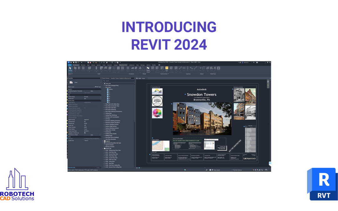
Revit 2024 has just been released, and with it are a lot of exciting new additions and improvements to existing features. We’ve highlighted several of the latest features you’ll come across.

To see all this in video format, click here: [link coming soon!]


Design productivity

  • My Insights in Revit Home
  • Dark Theme
  • New Imperial and Metric Templates
  • New sample model
  • Modernized Project Browser with new Search
  • Height parameter in scope box
  • Color Books browser
  • Textures visual style
  • Revit to Twinmotion enhancements
  • Site design – Icon reorg for Massing and Site
  • Site design – Create Toposolid
  • Site design – Generate Toposolid from Toposurface
  • Site design – Linked Topography enhancements
  • Site design – Contour Display settings per Types
  • Site design – Cut geometry enhancement & Mass Cut excavations
  • Site design – Solid Sub-divisions 
  • Site design – Cut & Split Toposolids
  • Site design – Graded Regions
  • Site design – Show shape-edit control points
  • Site design – Floor-based families and Slab Edges on Toposolids
  • Site design – Exposed Toposolid API
  • New path alignment options for free form rebar
  • Stirrup orientation for aligned free form rebar
  • MEP fabrication ductwork stiffener
  • Pipe Wall thickness as a built-in parameter
  • Elevation parameters in visibility filters
  • Hide insulation with hosting duct and pipe
  • Parameters sorting in type/instance properties
  • Export ‘Family type’ parameter

Simulation & analysis

  • Sun Settings in the ribbon
  • Run Solar Studies with seconds intervals
  • Sun Paths in perspective views
  • Generate energy model by view
  • Enhanced structural analytical loads
  • Structural area loads with color coding
  • Custom physical-analytical association
  • Detailed results for connection automation rules
  • Non-coincident loads for electrical analytical components
  • Flow and pressure calculations added to MEP fabrication network
  • Network based calculation for design ductwork
  • Demand loads for electrical analytical components
  • Flow and pressure drop calculations

Cloud data & interoperability

  • Link coordination models from Autodesk Docs
  • Manage links dialog for coordination models
  • Access properties of coordination model objects
  • Point snaps for coordination model objects
  • Collaboration cache relocation for cloud models
  • Link and Import PDF in Revit LT and Design Automation API
  • Revit to Robot Link enhancements

Design optimization

  • Dynamo for Revit 2.17 upgrade
  • Dynamo Player & Generative Design updates
  • Dynamo Player & Generative Design samples
  • Improved steel connections SDK documentation
  • Revit additional resizable dialogs
  • Revit Macro security improvements
  • API enhancements for developers

Documentation efficiency

  • Place multiple views and schedules on a sheet
  • Move aligned to sheet enhancements
  • Open sheet directly from drawing area
  • Schedule revision clouds
  • Align patterns on shaped-edited surfaces
  • Bar bending details on reinforcement drawings
  • Bar bending details in rebar schedules
  • 2D element draw order in 3D families
  • Resize all schedule rows
  • Enable removal of unit symbol for fraction inches

My Insights in Revit Home

  • New My Insights tab in Revit home page
  • Get personalized insights based on how you work and the work you do
  • Learn valuable information (new features, commands and workflows)
  • Display through cards
    • React to the cards
    • Learn more through the link in cards

Fresh from the Factory, Revit 2024 is rolling out globally! In this release, Autodesk has combined eagerly anticipated additions, like Site Tools for landscape designers, with highly requested enhancements from the community, like Dark Theme and a more modern user interface.

Here are three of the highlights from the new version:

Introducing Site Tools for Revit & Revit LT.

This new toolset supports the design and documentation of richly detailed landscapes. You can use Site Tools to:

  • Collect and rationalize existing conditions data from CAD Imports, CSV point files, and more.
  • Model your design intent freely and easily, with versatile site and massing tools for modeling topography.
  • Populate schedules, sheets, and views and calculate material quantities. Cut, fill, join, and run phasing scenarios. Use the design-to-documentation engine of Revit to save time and improve design quality when modeling landscape and site conditions.

Save time in concrete detailing.

Structural engineers and rebar detailers have new capabilities for creating, scheduling, and documenting rebar. Use the new bar bending details to:

  • Create reinforcement drawings and schedules with detailed fabrication instructions. With this new tool in Revit, when the model changes, the details adapt along with it.
  • Add and customize rebar bending details so that your views and sheets respect your typical practice.
  • Reduce errors and omissions in your document sets.

Evolve work together.

Link Coordination Model from Autodesk Docs into Revit makes it easier for project teams to sync and coordinate design deliverables. Keep project files light and teams on the same page.

  • Link models and views from any of the 60+ formats supported by Docs and the Autodesk Construction Cloud directly into Revit.
  • Underlay the coordination model as visual reference when designing in Revit.
  • Reduce the need for interpretation when coordinating up-to-date design deliverables with partners and project teams.   
Introducing Revit 2024

Introducing Revit 2024

Fresh from the Factory, Revit 2024 is rolling out globally! In this release, Autodesk has combined eagerly anticipated additions, like Site Tools for landscape designers, with highly requested enhancements from the community, like Dark Theme and a more modern user interface.

Here are three of the highlights from the new version:

Introducing Site Tools for Revit & Revit LT.

This new toolset supports the design and documentation of richly detailed landscapes. You can use Site Tools to:

  • Collect and rationalize existing conditions data from CAD Imports, CSV point files, and more.
  • Model your design intent freely and easily, with versatile site and massing tools for modeling topography.
  • Populate schedules, sheets, and views and calculate material quantities. Cut, fill, join, and run phasing scenarios. Use the design-to-documentation engine of Revit to save time and improve design quality when modeling landscape and site conditions.

Save time in concrete detailing.

Structural engineers and rebar detailers have new capabilities for creating, scheduling, and documenting rebar. Use the new bar bending details to:

  • Create reinforcement drawings and schedules with detailed fabrication instructions. With this new tool in Revit, when the model changes, the details adapt along with it.
  • Add and customize rebar bending details so that your views and sheets respect your typical practice.
  • Reduce errors and omissions in your document sets.

Evolve work together.

Link Coordination Model from Autodesk Docs into Revit makes it easier for project teams to sync and coordinate design deliverables. Keep project files light and teams on the same page.

  • Link models and views from any of the 60+ formats supported by Docs and the Autodesk Construction Cloud directly into Revit.
  • Underlay the coordination model as visual reference when designing in Revit.
  • Reduce the need for interpretation when coordinating up-to-date design deliverables with partners and project teams.   

Send us a message or just call us at 201-792-6300

Lets Connect