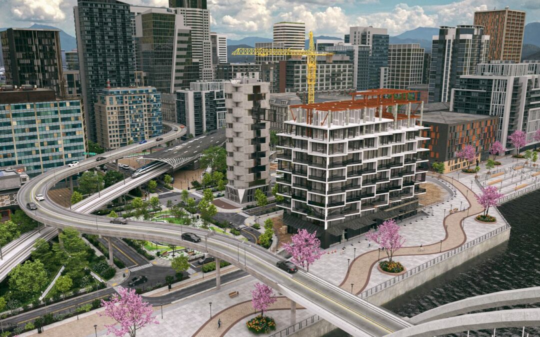
Architecture tools have come a long way since the days of pencils and paper blueprints. Still, some of the field’s most advanced and helpful resources remain underutilized. If you want to make the most of your 3D metal building designs, you should use building information modeling (BIM).
BIM software offers a suite of tools for creating, refining and sharing digital building designs and other project information. This extensive functionality offers several benefits over more conventional approaches to architecture, especially when you know how to use them to their fullest.
Photo by Nao Triponez
Benefits of BIM in 3D Metal Building Design
Metal building projects can be challenging and expensive, but BIM tools make it easier. Here is a look at some of this technology’s most significant advantages.
Fewer Mistakes
One of the most critical features of any BIM solution is clash detection. This technology automatically recognizes and highlights errors so you can address them before starting the construction process. Considering how large projects can have between 2,000 and 3,000 clashes, that can save a lot of time and money.
Some structures may take up more room than they seem at first, making them impractical or impossible in practice. Alternatively, some designs may block entry from needed machines during later parts of construction. BIM clash detection lets you find and fix these mistakes before they arise, preventing costly rework.
These features can also detect “4D” or workflow clashes like scheduling conflicts. That way, you can avoid complications later on when they’re harder to fix.
Optimizing Building Designs
BIM can also improve 3D metal building design by improving project visibility. This software lets you view plans from multiple angles, run simulations and easily compare alternatives. This level of insight enables you to find the best way forward for your specific project.
Having an easily accessible view of all the materials in a project can help make more informed decisions, too. For example, aluminum is one-third the weight of steel and more corrosion-resistant, but steel is stronger, making them ideal for different applications. With BIM, you can look at how each would impact your metal building design to optimize your project.
These optimizations apply to project workflows as well. BIM models provide a consolidated view of all relevant project information, helping schedule teams across various phases more efficiently.
Easier Collaboration
Another benefit of BIM is it enables more collaboration on your metal building projects. Because these tools are entirely digital, you can send them to collaborators via a simple file attachment in an email. Some cloud-based platforms may even let multiple parties simultaneously access and modify BIM models.
This remote access and sharing lets you work with other stakeholders regardless of where you are. Because everyone will be working off the same file, it also helps minimize confusion. Many of the most common project management problems arise from miscommunication and a lack of clarity, so these collaborative features are essential.
In the design phase, this collaboration lets everyone offer their expertise in the areas they’re most experienced. In later stages, it helps avoid conflict by providing a single source of truth for the project.
Streamlined Project Timelines
These advantages work together to produce another valuable benefit — shorter project timelines. The construction sector is notorious for running behind schedule, with 85.5% of large-scale projects finishing late, often by at least two months. BIM’s clash detection and collaboration tools can reverse that trend.
Rework is a common source of delays and BIM prevents it through clash detection. When you fix these clashes before the construction phase, you minimize the risk of an unexpected setback arising and taking time to undo them. Avoiding workflow clashes further reduces timelines.
Using BIM models as a single, easily accessible source of truth helps, too. When everyone involved uses these resources, it’s easier to stay on the same page and prevent miscommunication. Teams will finish faster as a result, boosting client relationships and minimizing costs.
Making the Most of BIM
It’s hard to ignore BIM’s potential in 3D metal building design. If you want to experience that potential to its fullest, here are some steps and considerations to keep in mind.
First, define what you want from your BIM software, then look for solutions that meet those goals. Keep compatibility with other apps you use in mind. The same goes for any sources you use for ready-made 3D BIM models. Only use content from companies that meet the highest industry standards to avoid complications down the road.
Look for a solution with cloud support. If it runs on the cloud, it’ll be easier to share models with remote collaborators or access them remotely. This accessibility will help further improve communication and project timelines.
While BIM will save money in the long run, upfront costs are the most common barrier to BIM adoption today. You can minimize these concerns through slow, thoughtful implementation. Start with a relatively simple solution, using it on projects with the most potential to improve. As you learn to use it and start to reap its benefits, you can hire more professionals to use it and buy more extensions for the software.
BIM Revolutionizes 3D Metal Building Design
BIM is a crucial tool for 3D metal building design, especially given frequent delays and high costs. When you know how to benefit from these tools, you can use them effectively.
As with any new tool, it can take time to get used to BIM. However, if you start today, you can boost your organization’s performance and ensure success in the future.
Momentum and money spur state Departments of Transportation to invest in digital project delivery.
Granular, interoperable, accessible data is the key to unlocking a completely new way of working in transportation.
New interoperability between Civil 3D and AASHTOWare Project is the latest example of Autodesk’s leadership in transportation infrastructure with organizations like AASHTO and Infotech.
Digital transformation has the power to connect data across the architecture, engineering, and construction (AEC) industry.
Many of the world’s infrastructure systems were constructed for the population and climate of the mid-20th century and are well past their prime. In the United States, much of our infrastructure dates back to the 1960s and 1970s and was designed and built using what are now outdated design, construction, and project management methods.
To modernize our infrastructure, we must modernize the engineering and construction industry itself with digitized workflows that enable better collaboration and seamless flow of data throughout the project lifecycle. We call this process digital project delivery. We are excited to work with states and the transportation technology ecosystem to make this monumental shift.
Advancing interoperability for better project outcomes
Digital transformation is about to accelerate for the government agencies that design, build, and maintain our nation’s transportation infrastructure through a new joint effort between Autodesk, Infotech, the American Association of State Highway and Transportation Officials (AASHTO), and the Montana Department of Transportation (Montana DOT). Initiated by Montana DOT, this collaboration underscores the agency’s commitment to embrace innovative technologies and enhance efficiency in the management and development of transportation systems.
Together, we’re enabling interoperability between Autodesk Civil 3D and AASHTO’s construction contract solution, AASHTOWare Project, with the help of Infotech, the official AASHTOWare Project contractor. The interoperability will enable digital project delivery from design and documentation to estimation and asset management. Departments of Transportation (DOT) across the United States and Ministries of Transportation in Canada will soon have access to it.
“With state transportation agencies in full pursuit of digital transformation, we’re excited to continue our work with Autodesk and provide an interoperable solution to those organizations,” said Chad Schafer, Chief Revenue Officer, Infotech. “This integration will help bridge the gaps in data and workflow between departments to ensure successful digital project delivery.”
Autodesk Civil 3D is civil engineering design software that supports BIM (Building Information Modeling) with integrated features to improve drafting, design, and construction documentation.
The interoperability couldn’t come at a better time. Momentum and money are finally on the side of the state agencies that are responsible for our transportation infrastructure. The Bipartisan Infrastructure Law will make a once-in-a-generation investment of $350 billion in highway programs through 2026. This includes the largest dedicated bridge investment since the construction of the interstate highway system 67 years ago.
The need for new infrastructure is urgent, with 1 in 5 miles of highways and major roads, and 45,000 bridges in the US alone in poor condition. State DOTs and the industry have more reasons than ever to transform the way transportation infrastructure projects are designed, built, operated, and maintained.
In a significant move, the Pennsylvania Department of Transportation (PennDOT), has established the Project Delivery Collaboration Center (PDCC), which is envisioned to be a Project Manager’s portal from project creation through final design, giving them visibility to details including, but not limited to, their project portfolio (two-week look ahead), cost (budget), dashboards and reviews. PennDOT has chosen to use Autodesk Construction Cloud as the primary tool for the PDCC. This decision, made with an agnostic approach, underscores a commitment to ensure compatibility and optimal performance across a broad spectrum of platforms, workflows, and systems.
Making data work for you
Data remains an untapped asset in engineering and construction, with consulting firm FMI reporting 96% of all data captured by the industry goes unused. But that’s about to change. The United States government is calling on state DOTs to use digital technologies such as cloud-based workflows, Building Information Modeling (BIM), GIS mapping systems, rapid construction, and digital project delivery.
States can compete for grants from the Federal Highway Administration’s Advanced Digital Construction Management Systems (ADCMS) Program to invest in technology that boosts productivity, manages complexity and cost, and delivers massive infrastructure projects quickly and safely. This ADCMS program will award $85 million in grants, showing a significant federal commitment to digital transformation.
At Autodesk, we believe that granular, interoperable, and accessible data is the key to unlocking digital transformation and driving a completely new way of working for engineering and construction teams. We simplified data management and collaboration by putting all our engineering and construction data in one location, Autodesk Docs, a common data environment that is open, secure, and accessible. Civil 3D is connected to Docs, supports BIM, and is integrated with GIS.
The new AASHTOWare Project integration closes a workflow gap by enabling state DOTs to take quantities directly from Civil 3D without error-prone and time-consuming manual entry. They can use GIS information in design, push the design information to project execution with AASHTOWare Project, pull actual quantities back to as-builts, and push data back into GIS for asset management.
“Interoperability between Civil 3D and AASHTOWare Project will help us connect our design phase to our field construction operations. It will save time, save costs, and ultimately, enable us to be more accountable to the taxpayers who fund our transportation projects,” said Patrick Lane, Digital Delivery Project Manager for the Montana Department of Transportation.
Granular, interoperable, accessible data is the key to unlocking a completely new way of working in transportation.
Advocating for the future of infrastructure
Autodesk is more than a technology vendor. We’re advocating for digital project delivery at the state and federal level. And we’re supporting states’ efforts to advance digital delivery for transportation projects. For example, the California Department of Transportation, Caltrans, is using Autodesk Connectors for ArcGIS to develop workflows between data sources to improve project delivery, and the agency recently received funding in the first round of FHWA’s ADCMS grants.
We also understand that states urgently need digitally skilled workers to successfully undertake digital transformation. So, we’re helping our partners empower current workers to be confident using the latest tools. And we’re working with DOT leaders and state engineering schools to make sure their graduates are ready for the digital future.
We’re here to help states deliver on this once-in-a-generation opportunity to transform how our nation connects communities and moves goods, people, and services.
Over the last ten years, Autodesk have integrated features into their product lineup to enhance customers’ creativity, automate repetitive tasks, and offer predictive insights through powerful analytics. “In 2024 and beyond, these capabilities will enable design and planning to become more effective, efficient, and better informed,” says Amy Bunszel. “For example, Autodesk Forma’s Rapid Operational Energy Analysis allows designers to understand how factors such as a building’s geometry and wall construction types will affect its predicted energy use–all during early stage design. Autodesk AI technology will help deliver better and more sustainable results for all.”
The expansion of Building Information Modeling (BIM) within construction is intricately connected to the upcoming fusion with AI. Despite its solid presence in design and engineering, BIM’s growing acceptance in construction is pivotal for optimizing AI in the industry. By serving as visual databases, BIM models gather abundant data from various construction phases, fortifying customer datasets and enabling more profound insights through AI.
Predictions for Emerging Tech in 2024
The utilization of emerging technologies like digital twins and virtual reality is gaining momentum in the construction sector. Digital twins are proving increasingly beneficial for owners and facility managers, offering support in areas such as remote asset management, predictive maintenance, and long-term asset planning. In response to the growing need for remote collaboration, Autodesk has introduced Workshop XR, a virtual reality workspace facilitating design reviews and issue identification before construction commences. This shift toward virtual reality explores enjoyable and efficient approaches to work, potentially shaping the future of work.
Construction firms are also exploring operational opportunities post-build, with digital twins providing rich data for informed decision-making by creating a comprehensive record from initial design to the completed structure. Additionally, augmented and virtual reality enhance the early evaluation of architectural outcomes during design reviews.
Read the full article from Autodesk: “2024 trends in the built environment: What to anticipate across AI, sustainability, and labor”, Amy Bunszel & Jim Lynch
As technology advances, architects need to combine technical know-how with high-level problem-solving.
Market pressures, technological advances, and climate change are driving the need for evolving skills in the architecture profession.
Students in architecture programs and junior architects will need to learn strong technology skills, gain an understanding of the history and theory of architecture, and develop high-level critical thinking to succeed.
As part of the job, architects will be called on to address the impacts of a project on its site, on nearby communities, and on global and local ecosystems.
The world is changing, and so are professions. The architecture, engineering, construction, and operations industry (AECO) is facing supply-chain issues, rising costs, labor shortages, and a high demand for buildings and infrastructure—and the architecture profession is evolving to meet these challenges.
But what do these changes look like? Accelerating technology, including machine learning and artificial intelligence (AI), is one aspect. Architects are also tasked with addressing their projects’ impact on the climate and communities, as well as how to build space- and resource-efficient structures. An understanding of technology and the ability to problem-solve at a high level will shape the skills architects need to thrive in the future.
Merging technology and critical thinking
Key among architect skills is a solid grasp of new software and tools. However, Phil Bernstein, associate dean and professor adjunct at the Yale University School of Architecture, cautions against putting too much emphasis on specific technical skills. “At Yale, we teach skills in support of training people to think like good architects,” he says, “but we know that a lot of the skills we teach have relatively limited shelf lives.”
This is not new. When Alistair Kell, chief information officer at BDP, graduated from architecture school in 1993, his class was the last that didn’t need to produce a CAD drawing in order to graduate. After graduation, he had to learn how to use AutoCAD, then a prerequisite for getting a job.
Original
1080p
720p
540p
224p
Today’s entrants to the job market are expected to have entirely new skills that are complementary to architecture, Kell says, like being able to use computational design, script and code, and understand data and data structures. But technological advances are already making it easier for architects to work with data without the ability to code. “If I want to write a Python script now, I just ask AI to write it,” Bernstein says.
In addition, many junior architects can easily leverage new tools for the projects they’re working on. “At this point, most students coming out of architecture school are digital natives, so they’re already adept at jumping from one technology platform to the next,” says Amy Perenchio, principal at ZGF Architects.
An ongoing need in architecture education will be fostering higher-level thinking among new architects. “Architecture is a profession where we solve problems, and technology assists in the solving of problems,” Perenchio says. “But critical thinking—in the design sense—is really the baseline skill set that is needed.”
Bernstein mirrors this idea: “What we’re really trying to do is teach these people to be next-generation thinkers about the built environment—what’s important about it and how to create it.”
For Kell, creativity remains a key component of being an architect, one he hopes the profession never loses. “Architects need to be able to leverage technology as a creative tool,” he says, “in the same way they would see a pencil or tracing paper as one of the fundamental aspects of how they express themselves and develop creative solutions.”
Using AI to support innovative design
One set of new tools that will have an outsize impact on the profession is machine learning and AI, though Perenchio says the industry is still in a phase of figuring out how to best bring these tools into practice.
David Beach, associate professor at Drury University, thinks AI will be “incredibly useful” as a technical tool, used to provide checks and balances and reduce the workload associated with modeling or redundant tasks, what Kell refers to as “the drudgery and repetition of what we do.”
Even more impactful, says Beach, will be AI for design creation. Where once it would have taken a team several months to generate 30 or 40 different design options, “now we’re getting that same kind of iterative design idea generation happening in minutes or hours,” he says.
Artificial intelligence can automate repetitive design tasks.
However, to use AI effectively as a design tool, he thinks there is a need “to establish a really strong understanding of precedent, analysis, and conceptual thinking.”
Kell agrees: “It’s not just about the software. The software is fundamental, but it’s the art of the architecture that really matters,” what he sees as “sensibilities around form, our own place, and our own materiality.”
“It’s important not to lose Vitruvius’s principles,” he says, referencing Roman architect Vitruvius’s three qualities necessary for a well-designed building: strength, utility, and beauty. “We can’t let technology drive us to a different outcome. The role of the architect is fundamental to enriching everybody’s lives, rather than simply supporting.”
Considering architecture’s impact on the world
One of the fundamental roles of architecture today is addressing human-driven causes of climate change. Bernstein says this broader approach is evident in how teaching architecture has shifted over the past 20 years from “making beautiful objects to making things in context.”
Design, he says, now involves “trying to understand what the relationship is between the thing that you’re designing and how it affects the larger systems of where it sits—on its site, in its neighborhood, in its city, and in a global ecosystem.”
Kell thinks new tools available to the profession will “help address some of the more fundamental challenges we’re all having, like how you better address climate change within your designs, and how you better calculate and reduce embodied carbon in your designs.”
In fact, addressing climate change is “all about data, and it’s all about digital solutions…that will normalize this for architects and engineers,” he says. “But it’s only going to come about through a greater understanding and adoption of technology.”
Beach also sees a need for architects, as “building experts,” to take on a larger role in adapting a building over its lifespan, based on both how the client is using it and how a changing climate affects a building’s performance.
Architects are increasingly called on to address climate change in their designs, such as using vertical or rooftop gardens to help regulate internal temperature.
In addition, given current supply-chain issues, labor shortages, and rising costs—and the potential for an influx of environmental refugees over the next two decades—he thinks students should learn skills that directly tackle these challenges. These include prefabrication and modular construction, Beach says. “Not that we think this is the future of everything, but we know that our students are going to have to be leaders in this.”
In addition to addressing climate change, Perenchio sees a strong need for finding “ways to engage the community so that marginalized groups can have voices at the table.” This makes it necessary for team members to have “a sense of empathy and emotional intelligence.”
While all architects need to consider the broader impacts of a project, Beach says the burden falls more heavily on the younger generations. “It is their responsibility to figure out how to usher us through these changes that are going to happen,” he says, and “to be responsible stewards of the environment and stewards of our communities.”
In the field of architecture and design, collaboration is crucial for successful project outcomes. With the advancement of technology, Building Information Modeling (BIM) has become a prevalent tool for designers, and Autodesk Revit has emerged as a leading software for BIM implementation. One essential feature within Revit that enhances design collaboration is Worksets. In this article, we will explore the significance of Revit Worksets in promoting efficient teamwork, streamlining workflows, and maximizing productivity.
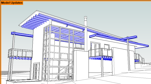
Credit: Autodesk | Use worksharing display modes to visually distinguish workshared project elements.
Streamlining Collaboration
Revit Worksets enable multiple team members to work on a project simultaneously, breaking down design tasks into manageable components. Each Workset contains specific elements of the building model, such as floors, walls, or MEP systems. By dividing the project into Worksets, designers can work concurrently on different aspects of the model without interference. This division allows for more focused and efficient collaboration among team members, ensuring smoother coordination and reducing the chances of conflicts arising from overlapping modifications.
Enhancing Design Productivity
One of the primary advantages of utilizing Worksets in Revit is the boost it provides to design productivity. The division of a project into Worksets facilitates parallel work, enabling team members to work on separate portions of the model simultaneously. This simultaneous work reduces downtime and accelerates the overall design process. For example, while one team member is developing the structural elements, another can focus on the architectural components, and yet another can handle the mechanical and electrical systems. By leveraging Worksets, designers can complete projects more efficiently, meeting deadlines and delivering high-quality designs.
Efficient Project Management
Revit Worksets also play a vital role in project management by allowing teams to control and track changes effectively. Each Workset can be assigned to specific team members, giving them exclusive access and responsibility for the elements within that Workset. This control ensures that modifications are made by the appropriate personnel, minimizing the risk of accidental or unauthorized changes. Additionally, Worksets provide a clear audit trail, enabling project managers to track changes, review progress, and resolve any conflicts that may arise during the collaborative design process.
Improved Design Coordination
Design coordination is essential to ensure that different building systems integrate seamlessly. With Revit Worksets, coordination between disciplines becomes more straightforward. Team members responsible for different disciplines, such as architecture, structure, and MEP, can focus on their specific Worksets while maintaining awareness of the overall project. By collaborating within their designated Worksets, designers can easily identify and resolve clashes, reducing design conflicts that may arise from overlapping elements. This streamlined coordination helps minimize errors, improves constructability, and enhances the overall quality of the final design.
Credit: Autodesk | Visually distinguish team members that own elements in a workshared project.
Learn More About Revit Worksets
In the realm of design collaboration, Revit Worksets have emerged as an invaluable tool. By dividing projects into manageable components and facilitating concurrent work, Worksets optimize teamwork, streamline workflows, and boost productivity. Moreover, they enable efficient project management, allowing for controlled access and effective change tracking. Revit Worksets enhance design coordination, ensuring seamless integration between different building systems.
With their multifaceted benefits, Revit Worksets have become an indispensable feature for architects and designers seeking to maximize collaboration and deliver exceptional results in the realm of BIM. Introduce Revit Worksets to your workflow with help from Robotech CAD Solutions. For 30 years, we’ve been delivering authorized training and certification to teams just like yours. See our course listing and reach out to get started today.


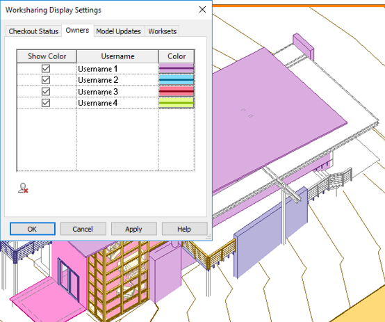 Credit: Autodesk | Visually distinguish team members that own elements in a workshared project.